Surface Layout Tab
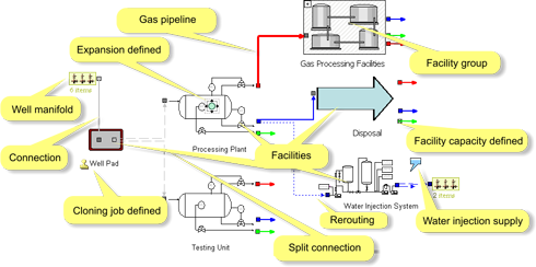
The Surface Layout tab displays a schematic layout of all surface facilities and connections, also indicating constraints on capacity and well manifolds connected to each facility. It allows you to define all aspects of the project related to the routing of fluids.
The display is schematic: unlike the reservoir Map Tab, the location of facilities, manifolds and connections on the Surface Layout is arbitrary and can be freely modified.
Each facility defined in the project is represented by the picture selected for it. If no picture has been selected, a generic "Load an image" message will appear. You can select a different image or a whole set of images from the Image Sub-Tab.
Some icons attached to facilities provide additional information:
 Cloning defined: This facility is scheduled to be cloned by an Automatic Development job or a Well & Facility Cloning job.
 Cloning by an Excess Policy defined: This facility is scheduled to be cloned by an excess policy; see Excess Policy Tab.
 Expansion defined: This facility may be expanded under certain conditions. See Excess Policy Tab.
 External water supply defined: See Injection Facilities.
 External gas supply defined: See Injection Facilities.
 Facility Construction / Pipeline Laying job deactivated. See Scheduling Pane.
A facility normally has a series of connectors, which represent its ability to receive and send fluids through the system. They are divided into  in and
  out connectors, represented by squares that follow a simple color code: oil,
  gas,
gas,  water,
  three-phase, etc. As can be seen, out connectors have a slightly lighter color than in connectors, and an arrow starting from it which indicates the destination of the processed fluids. See further under Connectors and Connections.
Facility capacity limits are displayed thus:  in out connectors, since they represent the facility's ability to deliver fluids. Selecting a node will display the fluid type and capacities if any. See Capacity Sub-Tab.
Connections between facilities are represented by colored lines from an out connector to an in connector; the color code is the same as for connectors. Line types indicate:
 simple: Generic connection with no further specifications.
 dashed: Split Streams.
 dotted: Fluids subject to rerouting. See Facility Production Rerouting job.
 thick: Pipeline, i.e. connection with defined construction costs and time. See Pipelines.
Wells are represented as  manifolds, that is, groups of wells connected to a facility, whether feeding it raw fluids (production wells) or receiving injections fluids from it (injection wells).
Finally, facilities can also be arranged as  Facility Groups. The arrangement of facilities in groups does not affect the routing of fluids but serve the purpose of simplifying the layout. Group images have non-editable icons and lines for all the connectors and connections of the facilities contained in it.